Distortion, Residual Stress, And Fixturing
Laser welding’s concentrated heat input significantly reduces distortion compared to MIG or TIG welding, but stainless steel’s thermal expansion rate (~17 µm/m·℃) is still almost 1.5× that of carbon steel. This means even small temperature changes can cause measurable movement. Residual stresses form when the weld metal and surrounding base metal cool and contract at different rates, and without proper fixturing and sequence control, these stresses can bend, twist, or warp the workpiece.
Controlling distortion and residual stress is about managing how heat is introduced and restrained—using fixtures, clamps, tack welds, and optimized weld paths to balance shrinkage forces while still allowing controlled expansion.
Clamp Smartly
· Function: Hold components in exact alignment and ensure consistent joint fit-up during the welding cycle.
· Advanced Practices:
1. Modular fixturing systems allow for quick reconfiguration for different parts, with integrated stops for repeatability.
2. Use heat-sink materials (copper, aluminum) in contact areas to draw away excess heat—reduces localized distortion.
3. Employ compliant clamping for long components, allowing slight longitudinal movement to prevent high locked-in stresses.
4. Ensure clamping surfaces are smooth, non-contaminating, and corrosion-resistant to avoid stainless staining.
· Pro Tip: For thin sheet assemblies, apply clamps in a symmetrical pattern around the weld zone to distribute restraint evenly.
Sequence
· Why it matters: Welding shrinks the metal along the joint length; the more uneven the heat distribution, the more likely the part will pull or twist.
· Control Strategies:
1. Backstep welding: start each short weld segment ahead of the previous stop and weld backward toward it, balancing heat flow.
2. Opposite-side balancing: weld corresponding joints on opposite sides of a part to offset shrinkage forces.
3. Skip welding: alternate between non-adjacent welds to allow cooling between heat inputs.
4. For box or tubular frames, weld small sections on each side in rotation rather than completing one seam entirely before moving on.
Tacks
· Purpose: Temporary welds that prevent parts from shifting between clamping and final weld.
· Technical Guidance:
1. Tack spacing for thin sheet (<2 mm): every 50–100 mm. For thicker sections (>5 mm): up to 250 mm, depending on rigidity.
2. Use fusion tacks (no filler) for precision fit-up, or filler-assisted tacks when gap filling is required.
3. Grind or smooth tacks if they will be outside the final weld bead to prevent stress risers.
4. For automated production, laser tacking is ideal due to its high precision, low heat, and repeatability.
Path Planning
· Impact on stress distribution: The order and direction of weld passes determine how shrinkage accumulates.
· Best Practice Approaches:
1. For flat sheet assemblies: weld from the center outward to let stresses dissipate toward the free edges.
2. For ring-shaped or circular components: weld in opposing sectors to balance radial contraction.
3. For multi-joint assemblies: sequence welds to avoid locking in distortion before all joints are complete.
4. Use CAD-based thermal simulation in robotic welding to predict movement and optimize the sequence before production.
· Special Note for Laser Welding: Because the process is so fast, thermal gradients can be steep; strategic pauses or temporary heat-sink placement can help balance cooling rates in sensitive components.
Residual Stress Management After Welding
· Post-Weld Measures:
1. For critical assemblies, low-temperature stress relief (typically <300 °C for stainless) can help reduce distortion potential without risking carbide precipitation.
2. In high-precision applications (e.g., aerospace instrumentation), post-weld machining or straightening may be required after natural cooling.
Stainless steel’s high thermal expansion means even low-heat laser welding can cause distortion and residual stress if not managed. In production, distortion prevention is not just about holding the part still—it’s about controlling how heat moves through the assembly. With laser welding’s precision and speed, applying these methods results in dimensionally accurate, stress-controlled stainless steel components with minimal rework.
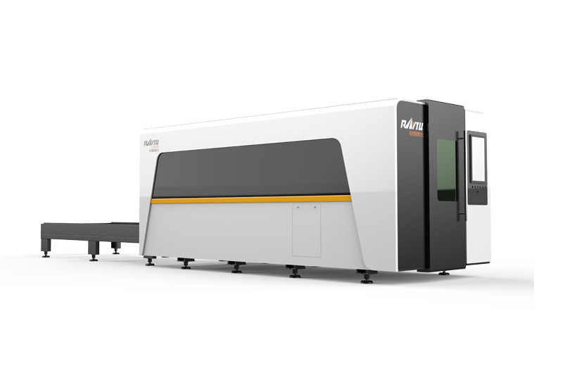 High Power Fiber Laser Cutting Machine
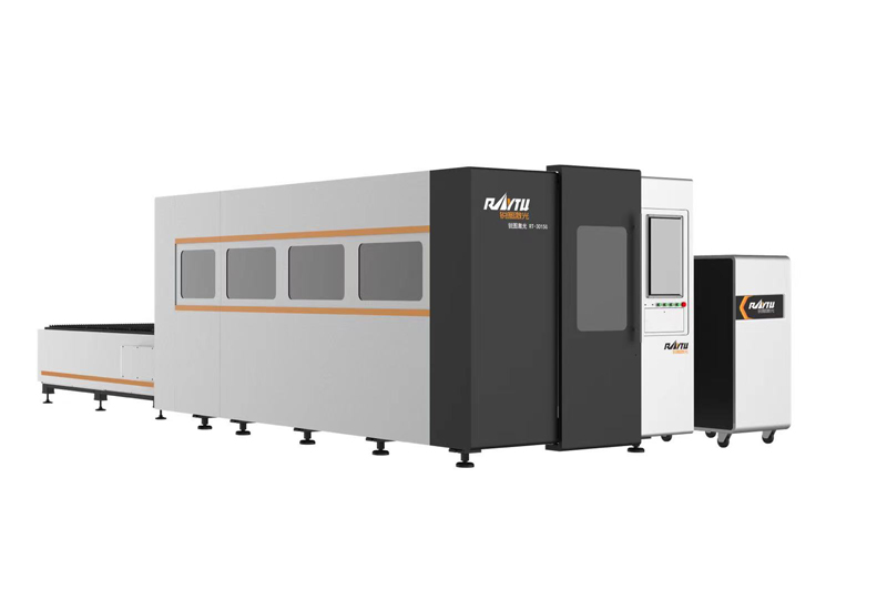 Enclosed Fiber Laser Cutting Machine
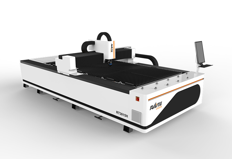 Sheet Metal Laser Cutting Machine
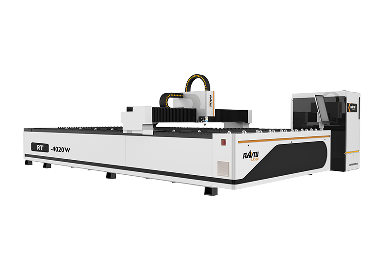 Medium Power Metal Laser Cutting Machine
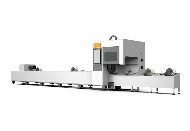 Automatic Tube Laser Cutting Machine
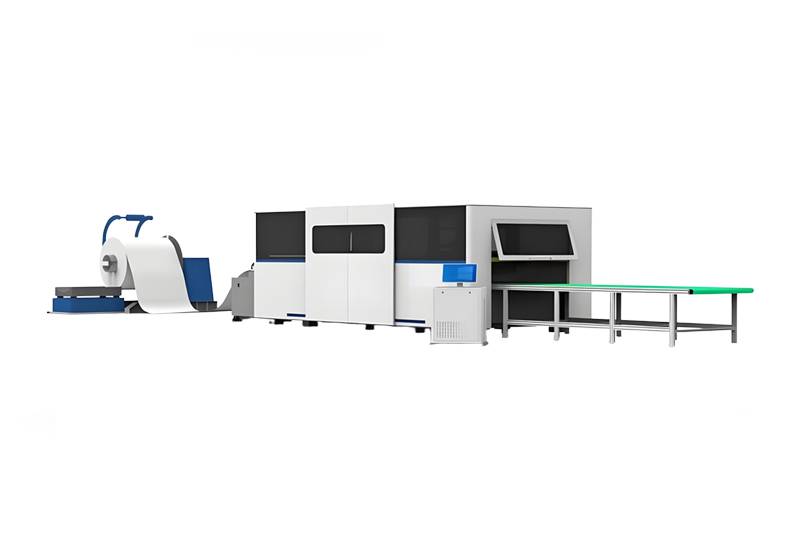 Coil Fiber Laser Cutting Machine
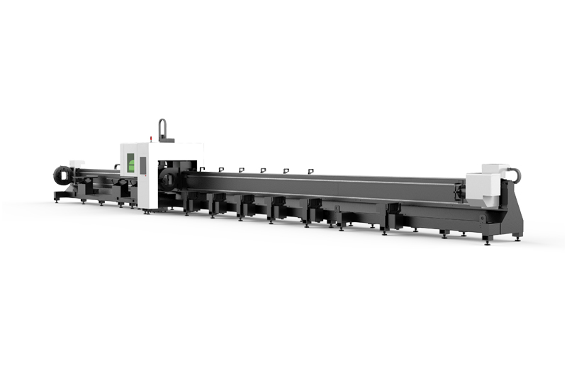 RTC-12036M 3 Chucks Tubeeber Laser Cutting Machine
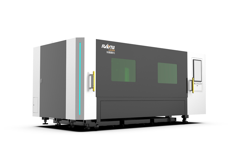 Single Table Enclosed Fiber Laser Cutting Machine


 EN
EN ES
ES RU
RU AR
AR